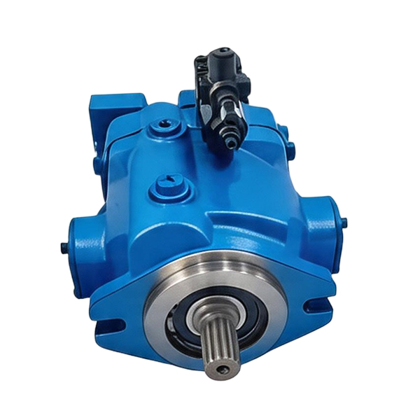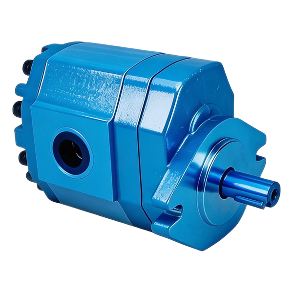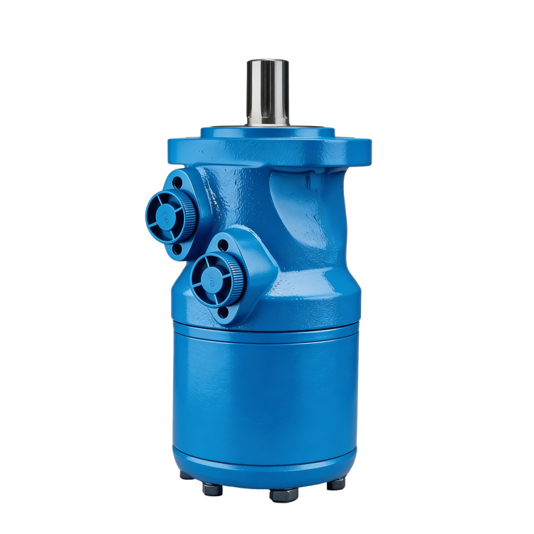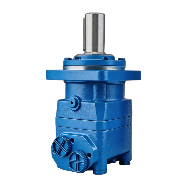

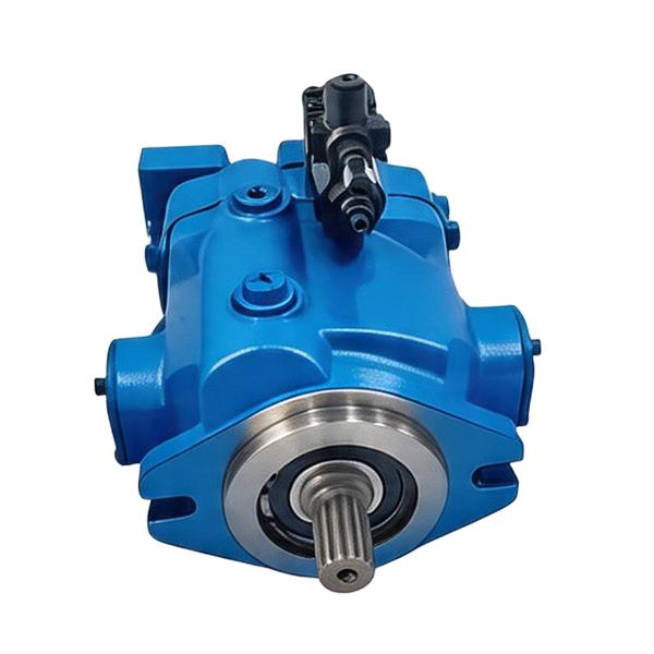
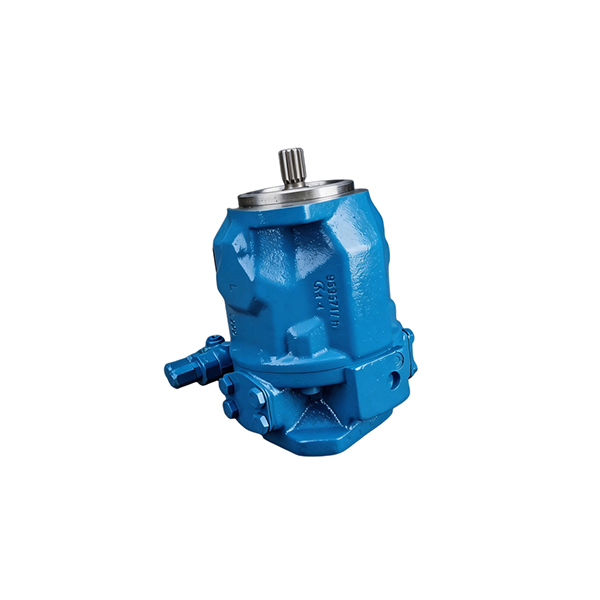
On a hi-lo hydraulic drive, the cylinder may move quickly until it meets the load, then slow down as pressure climbs. That change can be the expected two-stage hydraulic pump pressure transition. The larger pumping section stops contributing to the common delivery after unloading, while the smaller section continues to supply the loaded movement. Check the timing of the pressure rise, the reduction in delivery flow and the drive speed before deciding whether anything has failed.
Consider three complaints that sound alike over the phone. One cylinder slows exactly as it starts useful work and continues moving with adequate force. A second cylinder is slow from the moment the valve opens. A third slows because the engine loses speed and then stalls. Without the timing, all three arrive on the work order as “slow under load.” Keep the point where the motion first changed.
The method here is for reviewing a documented hi-lo circuit and interpreting measurements obtained by qualified personnel. Identify the approved machine procedure and safe load arrangement before using any instruments. The numerical records are hypothetical. Obtain the actual unloading specification, permitted working conditions and accepted measurement locations for the identified build.
Trace the common outlet and the unload route
Read the diagram from the two pumping sections to the valve and cylinder. In the common hi-lo arrangement used here, both sections contribute to the delivery at low load. When the unloading condition is reached, the larger section's flow takes a low-pressure route. A check function isolates that path from the common high-pressure delivery. The smaller section continues driving the load. The actual routes and sensing point come from the pump and machine diagrams.
An unload route can be internal. An externally visible tank hose might carry several flows or belong to a different function entirely. Draw the route from the circuit documentation before assigning any measured return flow to the large section. Preserve the distinction between a pump outlet, a cylinder work port and any accessible branch on the return side. Values at those positions can differ while the machine is operating correctly.
Concentric documents an internal unloading valve in its hi-lo family. Its US catalog also lists nominal flow at a stated shaft speed and separately lists unloading and maximum working pressure information for the units in that catalog. Read the row for the complete part number. That structure is a useful example for reviewing a quotation or a nameplate record. Concentric hi-lo pump family and Concentric US hi-lo pump catalog
Identify the device that sets each part of the sequence
| Circuit feature | Role in the assumed hi-lo arrangement | Evidence to obtain |
|---|---|---|
| Larger pumping section | Contributes most of the approach flow | Displacement or rated flow at the identified drive speed |
| Smaller pumping section | Supplies the working stage after unloading | Flow at the required loaded pressure and approved operating conditions |
| Unloading function | Redirects large-section delivery when its sensing conditions are met | Location, sensed pressure, transition definition and applicable range |
| Check function | Separates working delivery from the unloaded path | Flow direction and exact arrangement from the schematic |
| Machine relief | Limits pressure through its own bypass path when its conditions are met | Approved location, setting and pressure-flow behavior |
| Directional control | Sends flow to the active cylinder chamber and opens the opposite chamber's path | Spool position, port identities and any automatic return behavior |
A pump can share a shaft with another section yet feed two independent functions. In that arrangement a change in the pressure of one circuit need not cause a combined delivery to separate as in the hi-lo example. A drawing showing two outlets, two circuits and their valve functions carries more information than the words “double pump” on a label. If the documentation shows a different arrangement, use its own expected sequence.
Put each observation on the same stroke
Watch for the moment the load begins to resist motion. On a press this may be when the tool contacts the work. On a splitter it can be when the wedge enters a harder portion of the log. In a machine report the relevant event should be identified without asking an operator to reproduce a hazardous condition. Choose approved operating points and record whether the oil and drive were in comparable conditions.
The simplest useful trace has four channels or observations tied to the same time. Record common outlet pressure and delivered flow at defined locations. Record actual pump drive speed or an approved measurement that establishes it. Add cylinder position or speed and the relevant valve state. In many cases a fifth observation of cylinder work-port pressure resolves an apparent contradiction between pump pressure and load behavior.
| Phase | Pressure record | Flow and speed record | What the result can establish |
|---|---|---|---|
| Approach | Pressure required to move the mechanism before contact | Combined delivery where expected, plus shaft and ram speed | Whether the machine starts in its intended fast range |
| Load builds | Rise at the documented sensing or comparison point | Time of any change in common delivery | Whether the change accompanies the intended transition |
| Working stroke | Pressure required by the load | Smaller-section delivery and ram motion at the actual shaft speed | Whether the working stage supplies useful motion |
| End of work or release | Pressure decay in the applicable path | Recovery of flow where the circuit calls for it | Whether the expected state returns before the next cycle |
Pressure and flow maxima taken from different portions of the stroke do not form a working point. A slow-moving gauge may also miss a short change that a synchronized trace would show. Record the measurement method, instrument locations and any timing uncertainty. For a missing channel, record the resulting gap. A pressure trace with no speed reading leaves drive slowdown open.
Webtec describes using its RFIK tester to examine hydraulic pressure, flow and temperature. A test instrument is a means of collecting values. Its range and instructions need to fit the approved machine procedure, and the readings still require correct identification of the circuit state. Use qualified personnel and suitable equipment for any temporary test arrangement. Webtec RFIK mechanical hydraulic tester guidance
Separate the pressure that changes stage from the pressure that limits the machine
Keep a dedicated field for each pressure entry. The unloading condition belongs to the large-section flow transition. Working pressure belongs to the actual load and path while the cylinder moves. The machine relief has a different role and needs its own documented definition. The manufacturer's permitted pressures for the selected pump, cylinder, valve and connections constrain the whole test.
An unloader can have a stated opening condition and a transition over a range of flow and pressure. The criterion for detecting it should match the applicable documentation. A supplier might specify a particular measured flow change at a stated speed and fluid condition. A technician who writes only “switches at 45 bar” should also state what changed and where the pressure was measured. A gauge movement during tool contact can look like a transition before the outlet flow has settled.
The working stage needs enough pressure difference at the cylinder to move the load. At a relief-limited condition a portion of delivered flow may bypass useful motion. Detecting relief flow requires evidence from the relevant path or the approved test method. Heat in the return line is an observation to investigate, since several normal and abnormal flows can heat the same return plumbing.
| Pressure value in the record | Measurement or document basis | Interpretation |
|---|---|---|
| Load-contact pressure | Observation near the start of resistance | Describes this stroke and load |
| Unload onset or specified transition | Sensing point and defined flow response | Describes when the large-section path starts or completes its change |
| Loaded running pressure | Pressure at the named point while useful work continues | Describes load and losses at that condition |
| Relief behavior | Approved circuit information and permitted measurement | Describes the protective bypass at its operating condition |
| Maximum allowed pressure | Applicable selected-component and machine documentation | Constrains the procedure and candidate selection |
Keep the approved settings with the machine record. Diagnosis should begin with those settings and the observed sequence. Adjustments change the conditions under which the machine was evaluated and require the equipment manufacturer's instructions and authorized personnel.
Read an invented cycle from flow to motion
Take a fictional cylinder extending on its full bore. Assume an 80 mm bore, 40 L/min reaching the cylinder during approach and 11 L/min during the working stroke. For the first estimate, neglect leakage and assume the flows settle within each phase. The bore area is π × 80² / 4, or approximately 5,027 mm².
Convert L/min to mm³/s by multiplying by 1,000,000 and dividing by 60. Cylinder speed in mm/s is that converted flow divided by area in mm². The result predicts steady motion at the named chamber, so use the appropriate effective area for other configurations or directions.
| Phase in the hypothetical example | Flow at the cap end | Calculated extension speed | Illustrative travel and time |
|---|---|---|---|
| Approach | 40 L/min | About 132.6 mm/s | 300 mm in about 2.26 s |
| Loaded work | 11 L/min | About 36.5 mm/s | 80 mm in about 2.19 s |
The working segment is much shorter and takes nearly as long. In this example the change follows directly from the reduced flow reaching the cap end. Neither number includes delays from valve operation, pressure buildup, deceleration or return travel. A stopwatch measurement of the full cycle includes those phases and needs a separately defined comparison.
Now assume, for a force illustration, 170 bar at the cap end, negligible rod-end gauge pressure and no mechanical friction. The cap-end force estimate is 17 MPa × 0.005027 m², or about 85.5 kN. For an actual cylinder with rod-end pressure, subtract the opposing force using rod-side annular area, then account for friction and the mechanism as applicable. Retain both pressures and the areas used. That keeps a pump-side gauge reading from becoming an unsupported force claim.
A smaller working-stage flow does not in itself imply low force. One is primarily a speed input in this simple cylinder model, while the force estimate depends on chamber pressures and areas. A useful complaint record distinguishes “normal force with slower working stroke” from “insufficient force and slow movement.” The second observation leaves further load, pressure and flow questions to investigate.
Compare power at each stage on its own basis
Keep the assumed approach and work values in separate rows. For this illustration only, take 35 bar and 40 L/min at the common pump outlet during approach, then 170 bar and 11 L/min during work. Use outlet gauge pressure as the pressure rise for this simplified example, with inlet gauge pressure treated as negligible. Pressure at the cylinder would need its own measurement or a stated loss assumption.
| Hydraulic delivery term | Calculation | Result |
|---|---|---|
| Approach at common outlet | 35 × 40 / 600 | 2.33 kW |
| Working stroke at common outlet | 170 × 11 / 600 | 3.12 kW |
| Hypothetical combination absent from this cycle | 170 × 40 / 600 | 11.33 kW |
The third row pairs the flow from one stage with the pressure from another. Use the first two rows for the illustrated operating points. The actual drive requirement also depends on mechanical and hydraulic losses, the power absorbed by the unloaded section and what happens during the transition. A low-pressure circulation path still carries flow and can absorb power.
For an additional screening calculation, assume the unloaded section moves 29 L/min through a path with a 5 bar pressure rise. Its hydraulic power term is 5 × 29 / 600 ≈ 0.24 kW. Those values are assumptions for that branch. They cannot be obtained by subtracting one recorded outlet flow from another unless drive speed, leakage and the individual paths support the calculation. Calculate the complete shaft requirement with applicable performance data and the actual drive capability.
Read the engine or motor capacity at the working speed. During a shift a speed droop changes flow from both pump sections. If the drive slows before the recorded flow falls, investigate what caused that speed change. A flow reduction that follows load while the shaft holds speed can have a different explanation. Compare the two traces before ordering a pump to resolve a drive problem.
Slow from the first millimetre
When the cylinder is slow before it touches the work, start by confirming the commanded direction, actual drive speed and expected approach conditions. Note where the ram was when the operator first saw the problem. Compare the same part of a reference stroke at similar oil temperature and the same drive setting. Record the actual load on the mechanism, including any resistance during nominal approach.
If pressure is high before contact, mark the unloader’s sensing point on the drawing and compare its condition with the expected transition. Read the pump outlet and work-port values together. A large difference calls for a path check before assigning the whole outlet reading to the cylinder.
Correct drive speed and low outlet pressure make a smaller-section-like approach flow worth investigating. The circuit check should establish where the larger section is delivering, whether the unload path is open, and whether the combining check is doing its job.
If both stages are below expected flow, check the common conditions that affect both. Include drive speed, inlet supply, fluid condition and the instrument's location. An inlet problem may change with fluid temperature or with the total flow demanded. A single warm no-load result cannot establish what happens on a colder combined-flow stroke.
Fast approach, then weak work
The approach stage can look healthy while the working stage fails to meet the required load. Locate the change in common delivery, then review pressure and cylinder motion after it settles. An expected switch to the smaller section tells you that a flow change occurred. The subsequent pressure and motion tell you whether the machine does useful work.
In an illustrative work order, shaft speed holds and working pressure is available, yet the measured ram speed falls below the cap-end flow estimate. Confirm that the meter covers the active chamber. Then check valve state and rod-side pressure, and use the approved method to investigate leakage, bypass or mechanical resistance. A meter upstream of the valve leaves those branches unresolved.
If the pressure stays below the load requirement while a relief path is confirmed to pass oil, check the actual load and the specified relief behavior. Assign a pump replacement only when the component evidence and the required assembly support the order.
When the drive slows or stops
Put a cursor on the pressure rise and read the shaft-speed channel there. If the engine slows before the large section unloads, check the drive demand during that interval. Coupling and drive inspection follow the machine procedure. The sequence helps separate a late transition from a drive that cannot maintain its speed.
Mark recovery on the trace. The record may show a dip at pickup, a stable working stroke or repeated stops. Write the duration of the dip and what restores motion. A peak reading alone misses that distinction.
Repeated shifting around one load
For repeated switching, retain the rising and falling portions of the pressure trace. At each flow change, record the valve state and ram position. Compare the observed unload and recovery conditions with the definitions for the selected unit. Collect repeat runs only under the approved duty.
Pressure and flow oscillations can also reflect variation in the drive. Put the speed trace next to the pressure trace. Where an expected return to combined flow raises demand, a marginal drive may slow and change the pressure behavior again. That is a hypothesis to check against the time order. The actual machine could have a different pressure feedback path, so consult the schematic and approved test limits.
Record how much of the stroke is affected. A repeated change at initial contact and a repeated change throughout steady work imply different conditions to reproduce. A suitable report might state “three observed transitions in the first part of contact, stable motion afterward” and attach the timing and load information. The pattern provides a stronger basis for review than “pump hunts.”
Make the cold and warm results comparable
At a colder start, review the inlet path and pressure losses at the required combined flow. At warmer operation, look for a change in delivered flow at the same loaded point. Check both temperatures against the machine and fluid limits before comparing them.
Pair the same phase and direction at comparable shaft speed and load. If the first row is cold approach and the second is warm work, keep them as two operating observations. A second approach record or a second work record supplies the comparison that is missing.
Use the pump data for the stage conditions and the equipment manual for access, pressure release and service. The Champion 201549 manual gives a machine-specific example of operating and troubleshooting instructions.
Assign the next check from the trace
Route the case by the missing evidence. Send the pump reviewer a discrepancy at known speed, pressure and stage. Send the machine reviewer a measured drop between the outlet and actuator or a sequence problem. Send the test lead uncertain sensor locations or timing.
| Recorded pattern | First issue to resolve |
|---|---|
| Stable approach speed, a repeatable flow reduction at loading, then sustained useful work | Compare the sequence and working output with the applicable specification |
| Slow approach with a higher than expected load-contact pressure reading | Locate resistance and pressure losses during the approach |
| Low approach flow at correct speed and low pressure | Establish the actual large-section delivery and unloading state |
| Lower flow in both phases while shaft speed falls | Explain the drive slowdown and assess flow at the measured speed |
| Adequate pump outlet pressure with poor cylinder force | Measure or establish chamber pressures, effective areas and the load path |
| Normal initial work, then weakening as temperature changes | Recheck comparable hot and cold duty points, fluid and losses |
| Transition inferred from one gauge peak | Establish a valid flow or motion record with the relevant pressure and timing |
When only the gauge peak is available, send that observation with its location and ask which flow or motion measurement would distinguish the suspected states.
If the stage changes on cue but the pressure gap between the pump outlet and actuator is wider than expected under load, trace pressure loss through the hydraulic circuit under that working condition.
Build the replacement request around two working points
Begin with the complete pump code and machine identification. Record both expected delivery states with flow, pressure, shaft speed and oil condition. Mark the old and offered unloading arrangements and identify the condition under which combined flow should return. Include the machine drawing for the relief and relevant return or bypass paths. Attach the observed trace if the order follows a complaint.
Then compare interfaces. Record rotation with the drawing's viewing convention, flange, shaft and coupling, inlet and outlet connections, installation clearance and the correct support arrangement. Confirm rated inlet and speed conditions for the configuration. On a common inlet, approach flow can place the largest demand on the supply path. The hose and port arrangement must meet the applicable requirements at that phase as well as during the slower stroke.
Give purchasing the difference between an approved model, an offered candidate and an unknown. A catalog that gives only a nominal high-flow value leaves working delivery, unloading behavior and the applicable configuration unresolved. Ask for documents that tie those details to the exact offered part. A comparison of headline flow alone can select a pump that fits the flange but produces a different stroke time or drive load.
| Field to send | Why the supplier needs it |
|---|---|
| Model and circuit identification | Establishes the architecture and interfaces under review |
| Approach flow and working flow at stated speed | Sets two separate operating targets |
| Load pressure and transition condition | Defines the hydraulic demand and expected sequence |
| Drive speed and capacity under load | Supports review of the mechanical input |
| Cylinder data and timing target | Connects delivered flow with required motion |
| Evidence of the complaint | Helps identify the unresolved part of the cycle |
Use the two working points above to narrow down candidates in the BLINCE hydraulic pump range. Include the machine record when you request a review of the application so BLINCE can identify the exact build and supporting data for that duty.
Questions about a two-stage transition
Is the slower stroke always the high-pressure stage?
Locate the first slower movement on the trace. Normal unloading can reduce common flow as the load picks up and leave the ram moving under pressure. If motion was already slow on approach, review that earlier state. If shaft speed fell first, establish the drive condition.
Can I identify unloading from sound alone?
Keep sound as a timed observation. Combine it with common outlet flow and pressure at defined points, plus shaft speed and cylinder movement. The sound can help locate an event in a recording. The circuit evidence establishes the event's function.
Does the highest catalog flow determine pressing speed?
Use the flow available to the active chamber during the pressing phase. Take the applicable effective piston area and check the actual conditions and losses. In a documented hi-lo arrangement the smaller-section delivery often governs that part of the stroke. The combined nominal flow relates to a different state.
What is the shortest useful record to send with a service inquiry?
Attach the pump and machine identifiers, the point where the complaint starts, and the readings at that point. Show the pressure and flow locations on the schematic, and add drive speed, oil temperature and valve direction. Keep gaps visible in the report.