
Write the pressure beside the flow. A result of “47 L/min” leaves a hydraulic pump test half described: was that oil delivered at 20 bar or 160 bar, and at what shaft speed? Add the oil temperature and the pump's control state. With those conditions on the same line, the result can be compared with the required duty. Without them, a buyer has little basis for approving a repair or replacement.
The measuring point matters just as much. Oil measured before a priority branch is pump delivery. Oil measured after that branch is the supply available at the downstream connection. A difference between the two calls for an account of the branch flows; it cannot all be assigned to wear inside the pump.
This article is about reading and reviewing test evidence. The connection arrangement, loading sequence and stop limits must come from the applicable machine and pump procedure. A qualified technician needs to isolate the machine, release stored pressure and preserve required charge, pilot and lubrication supplies when making connections. Never improvise a blocked-outlet test to obtain a pressure number.

Give the test one question to answer
A slow attachment can send the investigation back toward the pump. Before removing it, define the check: delivered flow at the required working pressure, with the pump speed and control condition known. That gives the workshop a question it can answer from measurements.
List the pump assembly and control code beside the comparison document. The report can then say whether that identified unit met the output requirement at the recorded point. The attachment's remaining symptoms belong in the machine investigation.
Missing model data leaves an open acceptance criterion. Keep the pressure–flow observations, but leave the pass/fail box open until the comparison requirement is available.
Webtec's RFIK guidance describes a PQ test, comparing pump delivery as pressure is increased, and includes temperature in the comparison. Its pump check precedes investigation farther through the circuit. The test limit still comes from the machine, component and temporary-circuit requirements. Webtec RFIK testing guidance
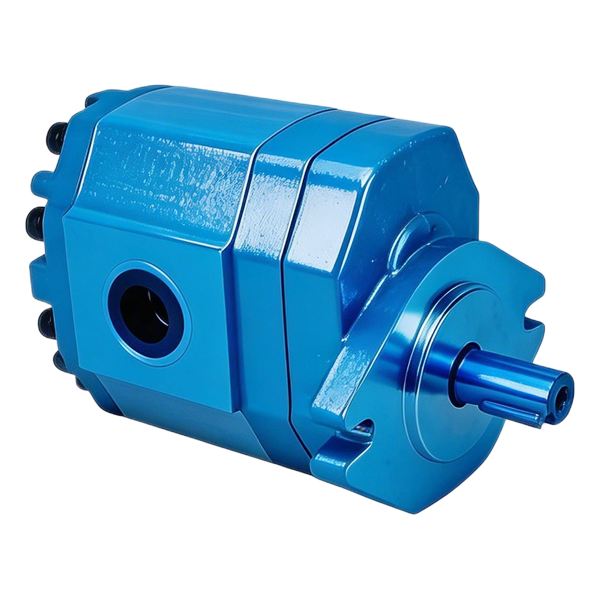
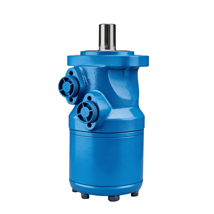
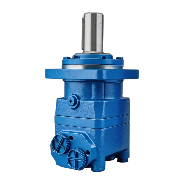
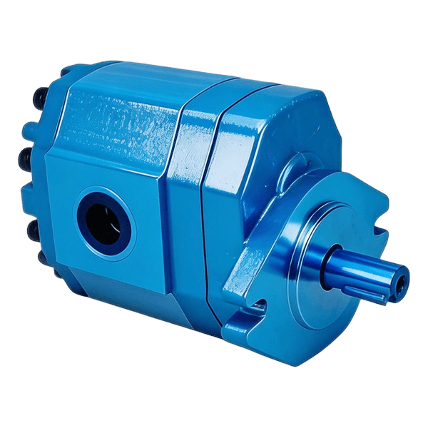
Start product identification from the appropriate family in the BLINCE hydraulic pump range. Gear, vane and piston pump pages serve different configurations. In particular, a variable pump operating under a pressure or flow command needs its control state identified before a displacement-based calculation can be interpreted.
Mark the measuring points on the circuit
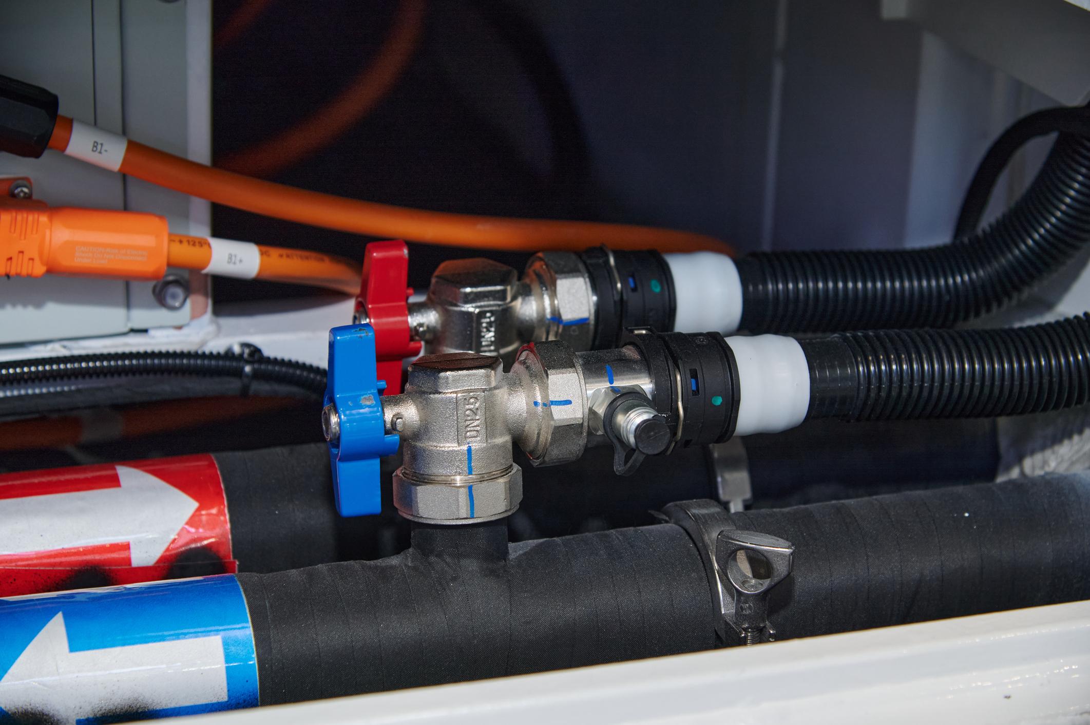
Where a steering branch leaves the delivery line, include that branch on the sketch. A line drawn straight from pump to attachment would omit oil taken along the way. Give the measuring points names that also appear on the test sheet; installation photographs can locate the corresponding hose connections.
An in-line tester still has a machine connected downstream. Its demands and controls remain in the investigation. A separate test arrangement substitutes a different loading path, which needs to be described in the applicable procedure.
Mark a steering or pilot branch where it leaves the measured path. Oil taken there has a destination before the selected actuator. The report needs to account for that destination when reconciling the two meter readings.
| Location shown on the sketch | Meaning of the reading | Context to retain |
|---|---|---|
| Pump delivery before the machine branches | Output crossing that point | Pressure, speed, temperature, pump control state |
| Supply after a priority or distribution branch | Flow available to the selected branch | Other active demands and upstream output |
| Inlet and outlet of a valve or connected path | Pressure difference across the named path | Flow, direction and valve position |
| Supply to the slow actuator | Oil reaching that function | Load, return condition and simultaneous demands |
| Applicable case-drain connection | Flow leaving the housing at that point | Pump design, included control flows and drain pressure |
Retain the pressure at each named connection. A loss between the pump and actuator requires a comparison across that path. Combining two gauge readings under “system pressure” conceals where the difference occurred.
Use the pressure difference across the component being assessed. The power example below uses an explicit approximation for pump inlet pressure because its invented test record supplies outlet gauge pressure.
Keep the operating conditions with each reading
The example's 1,500 rev/min belongs to the pump shaft during the reading. An engine setting taken before loading could produce a different pump figure once the drive ratio and any slowdown are accounted for. Identify how the reported speed was obtained.
Write “reservoir” or “pump inlet” beside the temperature, as applicable. The example's 50°C figure belongs to its stated inlet point. A tank reading needs its own label and the appropriate comparison data.
Add the command or control condition required by the procedure. If a variable pump has reduced displacement, its low delivery must be interpreted at that displacement. The full-displacement calculation used for a fixed pump would have the wrong basis.
Steering on for one check and idle for another introduces a different flow demand. Put the active functions alongside each operating point so the two sets of readings can be reconciled.
If a speed entry later proves wrong, the original readings allow the calculation to be revisited. Keep them with the diagnosis instead of retaining only the conclusion that the pump failed.

What a pressure gauge can leave out
An actuator held stationary while pressure is recorded supplies no evidence of the flow it would receive during a loaded movement. The gauge can show a satisfactory pressure while the delivery needed for the cycle remains untested.
An unloaded meter reading describes the low-load point. A complaint that appears during a loaded movement still needs the corresponding pressure and flow evidence.
A pressure-only test offer leaves that working delivery unresolved. Agree the required point with the repairer and use the approved loading arrangement. Raising a relief setting or plugging a line would change the machine rather than supply the missing measurement.
Select a useful measuring range
The weakest connected item sets the temporary circuit's limit. Check both the instrument's pressure capability and its flow range. A meter intended for a large main circuit may give an unhelpful reading of a small leakage flow. A meter chosen for that leakage flow may be unsuitable for the pump's full delivery. Range and resolution belong on the equipment review alongside fluid and temperature compatibility.
The instrument entries should identify which meter or gauge produced each column, with its relevant calibration information. On an electronic tester, state the type of value recorded. A saved peak can come from a different stage of the machine cycle than the steady value shown beside it.
Write units on every column. If a report contains a conversion, retain the source reading as well. “47” is ambiguous in a flow column with no unit, and the resulting power calculation will not repair the ambiguity.
Read a fixed-pump test without confusing two percentages
The following record is invented for arithmetic and interpretation, with no BLINCE rating, field result or replacement threshold implied. The example uses a nominal 36 cm³/rev fixed pump at 1,500 rev/min. Nominal displacement supplies the geometric basis; the delivery column contains the assumed meter readings.
| Invented point | Outlet pressure | Temperature at the stated inlet point | Measured delivery | Measured pump speed |
|---|---|---|---|---|
| A, low load | 20 bar | 50°C | 52 L/min | 1,500 rev/min |
| B, working load | 160 bar | 50°C | 47 L/min | 1,500 rev/min |
| C, changed thermal condition | 160 bar | 70°C | 42 L/min | 1,500 rev/min |
For displacement in cm³/rev and shaft speed in rev/min, multiplying the two and dividing by 1,000 gives the theoretical flow in L/min. Using that basis produces the following calculations from the same record.
| Quantity calculated | Substitution | Result |
|---|---|---|
| Geometric output basis | 36 × 1,500 / 1,000 | 54 L/min |
| B delivery / nominal geometric basis | 47 / 54 × 100 | 87.0% |
| B delivery / measured low-load A delivery | 47 / 52 × 100 | 90.4% |
| Nominal basis less B delivery | 54 − 47 | 7 L/min |
The 87.0% entry is a simple volumetric-efficiency estimate using nominal displacement. Follow the applicable performance method for an acceptance test, including a different displacement basis or corrections where required. The 90.4% entry describes retained low-load flow. Its denominator is the 52 L/min meter reading, so it answers a different question.
Likewise, the 7 L/min subtraction is a calculated gap against the stated geometric basis. It has not been measured in the case drain and must not be recorded as a case-flow measurement. The actual pump design and applicable test method determine how such a gap should be investigated.
Point C adds another issue. Pressure and speed match B, while temperature does not. The lower delivery describes a hotter operating condition. Compare that condition with the applicable data, and check the inlet, fluid and controls before assigning the whole difference to wear.

Account for a speed drop
Keep the invented pump's 36 cm³/rev displacement and consider a second speed of 1,350 rev/min, with an assumed delivery of 43 L/min. Put the two speed conditions beside one another before interpreting the four-unit difference in delivery.
| Invented condition | Shaft speed | Geometric flow basis | Assumed delivery | Delivery / geometric basis |
|---|---|---|---|---|
| Earlier working point | 1,500 rev/min | 36 × 1,500 / 1,000 = 54 L/min | 47 L/min | 87.0% |
| Reduced-speed point | 1,350 rev/min | 36 × 1,350 / 1,000 = 48.6 L/min | 43 L/min | 43 / 48.6 × 100 = 88.5% |
Using 54 L/min as the denominator in the second row would mix the two speeds. The drive slowdown accounts for a change in the geometric basis before pump condition is considered. Neither calculated ratio supplies a universal pass limit.
Scaling a flow reading to a reference speed can be a useful estimate, provided it is labeled that way. It does not reproduce a controlled test. Inlet behavior, leakage and controls may change with speed, so obtain a repeat at the required conditions when the decision depends on that comparison.
Recognize a pump control response
A variable pump can deliver less oil because its displacement has been reduced by a control. Before using the full nominal displacement in an efficiency calculation, establish whether that was the displacement the pump was expected to produce at the test point.
Pressure compensation is an example. As the pump approaches its controlled pressure, reduced delivery may be part of the intended response. Full-flow delivery and compensation are separate checks on that behavior. Two equal gauge readings can accompany different displacement states and therefore different delivered flows.
Parker's P1/PD A-mod service information separates delivered flow, case leakage and compensated operation in its test material. Speed and temperature conditions accompany those checks. The bulletin is useful evidence of how a manufacturer defines distinct test states; its values apply to the specified Parker models. They are not settings to copy onto a BLINCE unit. Parker P1/PD A-mod service information, July 2019
The control code belongs with the pump code in the report. Where a load-sensing signal or electronic command forms part of the approved test, retain that signal or command too. Removing the machine's demand signal to connect a tester can remove the very condition that the investigation needs to reproduce.
Output can be entered on the sheet while the efficiency cell remains blank. An unresolved control state is a reason to wait for that calculation: its displacement denominator has not yet been established.
Give a case-drain reading a location and a meaning
“High drain” needs a unit before it can guide the repair. High L/min and high bar describe separate observations. The sketch needs to show where each of those values was taken.
Whether the meter includes control or flushing oil is a question for the identified pump's drain-flow definition. Establish which flows reach that connection before using the total as a wear indicator.
Housing pressure needs a pressure measurement. An oil-flow figure gives no shortcut to it. A restricted path downstream can raise pressure at the housing, so retain the separate pressure observation with the drain-flow result.
Find the drain connection on the identified pump's port drawing. Vent and control connections have their own functions. The drawing and service procedure must provide for the external-drain arrangement being proposed.
An old drain reading without its temperature, speed or control state has a limited use. Keep it in the maintenance history, then obtain a comparable point before treating the difference as deterioration. A change of meter position also belongs in that comparison.
Ask the workshop which included flows and applicable comparison led to its repair recommendation.

Account for the flow between pump and actuator
Suppose an invented machine has 47 L/min measured before a branch and 32 L/min measured in the selected downstream supply. The difference is 15 L/min. It needs to be accounted for in the circuit outside the pump, because the first meter has already measured delivered oil.
A priority supply, another active function or a bypass path may be part of the account. The two readings do not identify which one. Before investigating a missing flow, confirm that the readings describe the same machine state. A steering action between tests can change the allocation without any change in pump condition.
| Entry in this invented flow account | Recorded quantity | Interpretation |
|---|---|---|
| Upstream delivery | 47 L/min | Flow crossing the first measuring point |
| Selected branch | 32 L/min | Flow crossing the downstream point |
| Difference requiring an explanation | 15 L/min | Allocation or another path between the points; destination still unknown |
The 15 L/min belongs to the account between the meter locations. Trace the other paths on the circuit and follow the approved method for checking them before assigning a destination to that oil.
Time matters as well as location. State how the operating point was reproduced if the meters were read in sequence. On a rapidly changing demand, two readings taken apart may never have existed together as one flow balance.
The hydraulic power unit pressure-loss guide covers the wider investigation through supply, control and actuator symptoms. A pump test contributes one defined result to that work. When the pump meets its applicable output requirement, retain that finding and move the investigation toward the affected path.
Use power to check what the loaded point represents
At the invented working point above, delivery is 47 L/min at 160 bar outlet gauge pressure. For this calculation only, take inlet gauge pressure as negligible. The pump's pressure difference is then approximated as 160 bar.
| Output-power calculation | Value used in this example |
|---|---|
| Pressure difference | Approximately 160 bar, with negligible inlet gauge pressure assumed |
| Delivered flow | 47 L/min |
| Metric relation | Power in kW = pressure difference in bar × flow in L/min / 600 |
| Substitution | 160 × 47 / 600 = 12.53 kW |
The 12.53 kW entry describes hydraulic output under the stated approximation. It is not a shaft-input measurement. Losses still belong in a separate assessment of the drive's required input.
A slowdown at this point still needs the shaft-speed record, drive information and other machine demands to be checked alongside the control. The output-power calculation supplies a working point, not an explanation of the slowdown.
The loading arrangement must also handle heat. Where oil passes through a restriction, pressure difference and flow describe the hydraulic power converted along that path. Use the local pressure difference for that restriction. Adding valve losses requires the separate pressure differences along their actual flow paths.
Temperature and duration therefore belong in the approved test plan, together with the cooling provision and temperature stops for the actual arrangement. Staying within a gauge's range does not establish an acceptable run duration.
Leave room for measurement uncertainty
Consider an instrument with an assumed uncertainty of ±2 L/min at the relevant operating point. A displayed 47 L/min then represents 45–49 L/min under that assumption. A display of 46 L/min represents 44–48 L/min. The two ranges share 45–48 L/min, leaving the one-unit display change inside that overlap.
Using the earlier nominal 54 L/min basis and treating that denominator as fixed gives this further arithmetic check. It considers the assumed flow interval only, without adding speed or displacement uncertainties.
| Flow used in the hypothetical interval | Calculation against the nominal basis | Result |
|---|---|---|
| 45 L/min, lower endpoint | 45 / 54 × 100 | 83.3% |
| 47 L/min, central reading | 47 / 54 × 100 | 87.0% |
| 49 L/min, upper endpoint | 49 / 54 × 100 | 90.7% |
The ±2 L/min interval was chosen for the illustration. A real report needs the selected instrument's value, its relevant calibration information and the conditions attached to that specification. Reading-based and full-scale-based accuracy statements can give different implications near the bottom of the range.
Reproducing a pressure point alone leaves other variables open. Retain speed and temperature too: changed speed affects the output basis, while changed viscosity can affect the hydraulic behavior. Those changes have to be separated from a proposed condition trend.
Keep the original inputs behind rounded calculations. Near an acceptance boundary, apply the agreed uncertainty and repeat-test method. Extra displayed decimal places do not improve the measurement.
If the result changes the repair decision, a controlled repeat has a clear purpose: reproduce the relevant condition and establish whether the finding holds. Record any change of instrument, connection point or control configuration. That makes the repeat a reviewable comparison instead of a second unexplained result.

Make the report useful to purchasing
Tie the machine equipment number to the complete pump assembly/control identity. Keep that connection on the paperwork if the unit goes to another workshop. The operating record and comparison requirement can then be traced to the same assembly.
| Report item | What a reviewer should be able to find |
|---|---|
| Purpose and comparison basis | The question being tested, applicable procedure and model data or approved baseline |
| Pump and machine identity | Assembly/control code, available serial information and equipment number |
| Measurement arrangement | A sketch with named points and relevant branches |
| Operating point | Paired pressure and flow, shaft speed, temperature location and control state |
| Equipment used | Instrument identities and relevant calibration/uncertainty information |
| Findings | Recorded observations, supported interpretation and unresolved items |
Leave an unobtained loaded point blank and state the stop condition that prevented it. A calculated estimate belongs in a separately labeled field, where a buyer can distinguish it from a completed measurement.
For a repaired pump, state the work performed and the configuration actually tested. A changed control or displacement setting can alter the comparison with the original machine requirement. The test report needs to follow the assembly that will be installed, not an earlier or convenient test configuration.
Keep the original measurements behind any summary. Another reviewer may need to revisit the speed assumption, identify a branch flow or check which pressure difference went into a power calculation. A label saying “tested good” cannot answer those questions.
Let the finding determine the next inquiry
Where delivery is short, the workshop still has to distinguish inlet, drive, control and internal causes. Parts for a repair follow that finding; the delivery number does not supply a parts list.
A satisfactory pump result redirects the next check downstream. An unresolved control response sends it toward control-specific information. Missing acceptance data leaves the pass/fail decision open until that data is obtained.
For a replacement inquiry, send the full pump code and control identification, its circuit role, required working points, drive/mounting information and the test report. Include the machine condition that produces the complaint. This lets a supplier review the required duty alongside the measured behavior, rather than select from an unrelated catalog maximum.
Use BLINCE's contact page for that defined request. Ask for a proposed configuration and the supporting information needed to compare it with the machine. Exact ratings, control options, availability and any offered acceptance testing need confirmation for that build.
Questions about the scope of a pump test
Can a pressure-only test establish working capacity?
It establishes the result of the defined pressure check. Working delivery still needs flow measured at the relevant pressure, with speed, temperature and control state recorded. Select the required test points from the applicable procedure.
Can a cold and a hot reading be compared?
They describe behavior at two thermal conditions, each with its corresponding comparison data. To investigate deterioration, obtain a repeat with comparable conditions and a stated temperature location.
Can efficiency be calculated without knowing the pump control state?
List the measured flow and pressure and identify the missing displacement basis. A full-displacement efficiency claim has to wait for that information. Leave any unobtained required test point identified as a gap alongside the available readings.